Contents
LED Street Light Uganda
PO Box: 73271, Plot No. 7629, Block 244, Tank-Hill Bypass,
Kiwafu Road, Kansanga-Muyenga, Kampala, Uganda.
Re-Power Technical Services Ltd
P.O.Box 732,
RE-POWER TECHNICAL Services Ltd is a registered company in Uganda since 2005 to offer Engineering solutions and Technical Services in the region. Our company is engages in Road Traffic signals and we represent Siemens ITS (UK), Nippon Signal (JAPAN) and TSEC (JAPAN) in Uganda
- SOLAR STREET LIGHTING SPECIFICATION
Luminaires
| S/n | Description | Specifications |
| 1 | Luminaire Power rating | 75 |
| 2 | Luminaire efficiency (lumen) | Min 130 l/w |
| 2 | Lifespan | 15 years |
| 3 | System voltage | 12 |
| 4 | Luminaire Housing: | marine grade high-pressure die-cast aluminum alloy to EN 1706 AC-44300 |
| 6 | Surface finishing | Gray Paint RAL7040 |
| 7 | Gasket: | Heat resistant silicone rubber (No glue) |
| 8 | Glass: | Tempered Glass |
| 9 | Luminaire glass Thickness | > 4 mm |
| 10 | Luminaire glass Light transmittance | > 92% |
Batteries
| S/n | Description | Specifications |
| 1 | Battery type | Grade A Lithium Iron Phosphate, LiFePo |
| 3 | Battery Capacity at 77ºF (25ºC) | ≥1229 Watt Hours or 150 Ah whichever is higher |
| 4 | Battery management system (BMS) | MUST INCLUDE |
| 5 | Battery installation | All in One or Integrated in Solar Panel with a minimum IP65(1m, 720hours)- NO GROUND INSTALLATION |
| 6 | Battery life cycle@25% DOD | Min 4000 |
| 7 | Battery Rated Voltage | 12V/24V |
| 8 | System voltage | 12V/24V |
| 10 | Discharge rate @ 10hrs | 25.0A,10.8V |
| 11 | Average-Self discharge Rate, per month, 77ºF (25ºC) | <2% |
| 12 | Charge Temperature Range | -20ºC to 55ºC |
| 13 | Discharge Temperature Range | -10ºC to 55ºC |
| 14 | Storage Temperature Range | -20ºC to 55ºC |
| 15 | Max Charge Current | 62.5A |
| 16 | Temperature Compensation | 18-24 mV/ºC/pcs |
Photo Voltaic (PV) Module
| S/n | Description | Specifications |
| 1 | Cell type | Mono crystalline, solid blue |
| 3 | Max wind load (Pa) | 2.4kN/m² |
| 4 | No of PV modules per single arm light | two |
| 5 | Total Power | 260 W at peak |
| 8 | System Voltage Range | > 1000 V |
| 9 | Operating Current | 8A |
| 10 | Short Circuit Current | 8.43A |
| 11 | temperature, C | -10 to +85° |
| 12 | Humidity | 5% – 95% RH |
| 13 | Panel cable connector | ≥IP66 |
| 14 | Solar Cell Efficiency | > 15.9% |
| 15 | PV Module efficiency | > 14% |
| 16 | Failure Rate | 0.0001 |
| 17 | Certification | TUV, ISO and UL |
| 18 | Warranty | 25 years |
Regulator (Charge Controller)
| S/n | Description | Specifications |
| 1 | Type | Charge controller to have Remote meter.
The charge controller has dual display function: Local LCD and a remote meter. The remote meter works with RS485 Communication bus interface and zigbee 3.0 communication protocol |
| 2 | GSM Mode | 2G (GPRS/CDMA), 3G (WUCDMA/HUUPA/HSPA+/CDMA 2000 1 x EVDO), 4G(FDD-LTE/TDD-LTE) |
| 3 | Wireless Network | GSM/GPRS/EDGE: 850/900// 1800/ 1900 MHz |
| CDMA: 800/1900 MHz | ||
| WCDMA/HSUPA/HSPA+:850/900/1900/2100 MHz | ||
| TD-SCDMA: 1880- 1920/2010-2025 MHz (A/F) | ||
| FDD-LTE: Band 1/3/5 | ||
| TDD-LTE: Band 38/39/40/41 | ||
| CDMA 200 1 x EVDO Rev.A: 800/1900 MHz | ||
| 4 | Sim Card Slot | Standard Drawer Layout Interface (Like Cellphone Sime Card Slot) |
| 5 | Communication Protocol | TCP/UDP Protocol |
| 6 | Emitting Power | GSM900-2W, DCS-1800, 1W |
| 7 | Receiving Sensitivity | -100dBm |
| 8 | Antenna Interface | Standard SMA female Antenna Interface, characteristic resistance, 50 Ohms |
| 9 | Minimum Line Transmit Distance | 1.5km |
| 10 | Monitoring and Control Software | Customized to be locally installed at KCCA nd not remotely. Central control of software should be installed locally at KCCA for control, monitoring, querry parameters, set parameters, broken alarm, users admin, lamp location on map, Historical report.
License should be handed over to KCCA after installation |
| 11 | Nominal Voltage | 12 V / 24 V automatic recognition |
| 12 | Day/Night Time Configuration | Automatic |
| 13 | Power Supply | Grid Power and Solar Power Supply for light and other DC loads |
| 14 | Max conversion efficiency | Solar power first, grid power second to compensation |
| 15 | Max Charge / Load Current | 20-30 A |
| 16 | Conversion efficiency | 98% |
| 17 | Max conversion efficiency | 99.5% |
| 18 | Float Voltage | 13.8 / 27.6 V (25ºC) |
| 19 | Boost Voltage | 14.4 / 28.8 V (25ºC), 2h |
| 20 | Boost Cycle Activation | If battery voltage goes below 12.3V / 24.8V |
| 21 | Equalization Voltage | 12.8 / 29.6 V (25ºC), 2h |
| 22 | Equalization Cycle Activation | If battery voltage goes below 12.1V / 24.2V |
| 23 | Additional Equalization | Every 30 days |
| 24 | Load Disconnect Voltage | 11.00-12.02V / 22.00-24.04 V |
| 25 | Load Reconnect Voltage | 12.8 V / 25.6 V |
| 26 | Battery over voltage protection | 15.5 V / 31.0 V |
| 27 | Emergency switch off | <10.5 V / 21 V |
| 28 | Max Solar Voltage | 100 VDC |
| 29 | Temperature Compensation | -4.2 mV/K per cell |
| 30 | Max Self-Consumption | 8mA@12V, 10mA@24V |
| 31 | Ambient Temperature Range | -40ºC to 85ºC |
| 32 | Battery Type | Lithium Phospate Iron |
| 33 | Evening / Morning Hours Range | 0-15 h / 0-14 h |
| 34 | Night / Day Detect Range | 2.5-10V |
| 35 | IP rating | IP66/IP67 including all connector |
| 36 | Protection | |
| Battery Reverse Polarity Protection | ||
| Battery Overcharge Protection | ||
| Load Short-Circuit Protection | ||
| Load Overload Protection | ||
| PV Reverse Polarity Protection |
Street Light Poles
| S/n | Description | Specifications |
| 1 | Material | Steel |
| 2 | height | 9.0m |
| 3 | Type | Round Tapered |
| 4 | Lower Aperture | 200 mm |
| 5 | Upper Aperture | 100 mm |
| 6 | Metal thickness | 4.2 mm |
| 7 | Length of Lamp Arm Brackets | 1200 mm |
| 8 | Bracket Overhang (m) | 0.8 |
| 9 | Arm Length (m) | 1m |
| 10 | Luminaire Tilt Angle (degrees to the horizontal)* | 30 degrees |
| 11 | Luminaire mounting height(m) | 8.0 |
| 12 | Treatment and finish | hot dip galvanizing 70µm – topped up with epoxy coating |
Street light remote monitoring and control
SMART SOLAR LIGHT
COMMUNICATION SPECIFICATION
The lighting will be by solar with telemetry and remote control for switch off/on. The battery bank and communication gadgets will be hosted overhead.
| Purpose | To capture and transmit all telemetry of the charging system, battery system and lighting system. To also provide remote management and control; switch off/on, illumination control. This is as defined in the controller spec above |
| Normal Pole | Should collect telemetry data of its devices. Should receive data from nearby poles. Should aggregate data and forward it to nearby pole using Zigbee 3.0 or LoRa protocols or IEEE802.15.4 network protocol. Each normal Pole should be fitted with a IEEE802.15.4 transceiver. This transceiver should also support GSM/GPRS/UMTS. |
| Pole to Pole Communication | Poles should communicate with nearby poles with in a distance of at least 50m over a Zigbee 3.0 or LORA protocol wireless communication system supported by Ethernet IEEE802.15.4 protocol where applicable.
However the contractor could also use RF based mesh network for communication |
| Concentrator Pole | Should aggregate communication of at least 10 Poles and forward it to control center through Fibre. The Zigbee or LoRa or GSM (based on IEEE802.15.4) transceiver on the concentrator Pole should also support ethernet connection consistent with IEEE802.3 protocol in addition to GSM/GPRS/UMTS. Otherwise if using mesh network, this might not be necessary.
Concentrator pole power and communication requirements should be taken into consideration. A Fibre cable shall be run to the nearest Traffic control unit at a signal junction or control room directly to connect the concentrator Pole to the control Room. |
| At the control House for non-mesh based network | All the Communication Cabinet at the concentrator lights shall be connected to a Fibre switch which will then connect to control Centre through long range Fibre connection.
A 24 Port Fibre switch with at least 100MB SFP/LC SFP Ports shall be installed capable of pushing a Fibre signal for 5km. A direct Fibre cable will run from the switch to each Concentrator Pole capable of transmitting at 100MBPS. |
| Control Centre (HQ) | A management interface shall be installed locally to collect data from the lights and send management commands to the lights.
The management application should be able to run on a Virtualised server infrastructure as well as on a physical server. All licenses must be installed locally and handed over to KCCA |
9302 TESTS
After the completion of the work and before the first delivery is taken, a full test will be carried out on the installation for a period of 30 days to determine the satisfactory working thereof. During this period the installations will be inspected and the contractor shall make good, to the satisfaction of the Engineer, any defects which may arise.
The contractor shall provide all instruments and equipment required for testing and any water, power and fuel required for the commissioning and testing of the installations at completion.
9303 MAINTENANCE OF INSTALLATIONS
With effect from the date of the First Delivery Certificate the contractor shall at his own expense undertake the regular servicing of the installation during the Defects Liability Period and shall make all adjustments necessary for the correct operation thereof.
If during the said period the installation is not in working order for any reason for which the contractor is responsible, or if the installation develops defects, the contractor shall immediately, upon being notified thereof, take steps to remedy the defects and make any necessary adjustments.
Should such stoppages however be so frequent as to become troublesome, or should the installation otherwise prove unsatisfactory during the said period the contractor shall, if called upon by the Engineer or the Employer, at his own expense replace the whole of the installation or such parts thereof as the Engineer or the Employer may deem necessary, with apparatus specified by the Engineer or the Employer.
9304 REGULATIONS
The installation shall be erected and tested in accordance with the following Acts and regulations:
- OHSAS 18001:2007 – Occupational Health and safety certification.
- IEC 61478 Live working – Ladders of insulating material
- IEC 61482 Live working – Protective clothing against the thermal hazards of an electric arc
- IEC 61642 Industrial a.c. Networks Affected by Harmonics – Application of Filters and Shunt Capacitors
- IEC 61643 Surge protective devices connected to low-voltage power distribution systems
- IEC 61646 Thin-film terrestrial photovoltaic (PV) modules – Design qualification and type approval
- IEC 62041 EMC requirements for power transformers, power supplies, reactors and similar products
- l) The Local Government and the municipal by-laws and any special requirements of the local KCCA supply authority,
- j) IEC 61427 Secondary cells and batteries for renewable energy storage – General requirements and methods of test
- k) IEC 62109 Safety of power converters for use in photovoltaic power systems
- l) IEC 62262Degreesof protection provided by enclosures for electrical equipment against external mechanical impacts
- m) IEC 62455Internet protocol (IP) and transport stream (TS) based service access
9305 NOTICES
The contractor shall give all notices required by and pay all necessary fees, including any inspection fees, which may be due.
9306 SCHEDULE OF FITTINGS
In all instances where schedule of light, socket outlet and power points are attached to or included on the drawings, these schedules are to be regarded as forming part of the specification.
9307 QUALITY OF MATERIALS
Only materials of highest quality shall be used and all materials shall be subject to the approval of the Employer. The Employer’s specifications for various materials to be used on this Contract are attached to and form part of this specification.
Wherever applicable, the material shall comply with the or to British Standards Specifications, or IEC standards where no British Standards exist.
Materials wherever possible, must be of African manufacture.
9308 WORKMANSHIP AND STAFF
Except in the case of electrical installations supplied by a single-phase electricity supply at the point of supply, a Registered Engineer by the Engineering Registration Board of Uganda shall be part of the contractor’s staff to supervise, certify and hand over the installation.
Any civil works that might be different from the available drawings will be done following certified drawing by a Civil Engineer registered by the Engineer’s Registration Board of Uganda at the expense of the contractor.
All inferior work shall, on indication by the Employer’s inspecting officers, be immediately removed and rectified by and at the expense of the contractor.
9309 CERTIFICATE OF COMPLIANCE
At each phase of working, prior to any clearance for payment, checks will be made in accordance to the availed specification and standards of engineering practice of Uganda and/or British Standards.
On completion of the service, a certificate of compliance shall be issued to the Employer reflecting full compliance with the requirements of KCCA, defined specifications and applicable standards.
SECTION 9400: INSTALLATION DETAIL
TABLE OF CONTENTS
ITEM DESCRIPTION
9400 BRIEF SUMMARY OF THE WORK TO BE DONE
9401 NOTICES
9402 ELECTRICAL EQUIPMENT
9403 DRAWINGS
9404 BALANCING OF LOAD
9405 SERVICE CONDITIONS
9406 LIGHT FITTINGS AND LAMPS
9407 EARTHING AND BONDING
9408 MAINTENANCE OF ELECTRICAL SUPPLY
9409 SUPPLY AUTHORITY
9410 SUPPLY VOLTAGE
9411 FEEDER CABLES
9412 CABLE SLEEVES
9413 DISTRIBUTION KIOSKS
9414 DISTRIBUTION KIOSK AND EQUIPMENT
9415 INSTALLATION OF LUMINAIRES
9416 HIGH MAST LIGHTING
9417 CORE DRILLING
9418 ASPECTS THAT NEED SPECIAL ATTENTION
9419 SAFETY REGULATIONS
9400 INSTALLATION DETAIL
The requirements in this section of the specification are supplementary to the Quality Specification and take precedence over the requirements in the Quality Specification of this specification, but must be read in conjunction with the rest of the document.
9400 BRIEF SUMMARY OF WORK TO BE DONE
The project consists of the installation of 9m mounting height poles with spigot configuration for installation of a 260W solar panel integrated with battery, regulator box, outreach arm and LED luminaires within Kampala city to be in compliance with IEC 61215
The Electrical work shall include the following:
- Supply, install, test and commission the lighting scheme consisting of 9m mounting height poles and approved solar power luminaires including solar panel with battery integrated in the solar panel or have an all in one configuration with panel, controller luminaire and battery integrated as one. These are as shown below;
Figure 1: All in One Solar Street Light Configuration Schematic for elucidation purposes
Figure 2: Split integrated with Battery and charge controller integrated with solar panel and light split on arm
- Commissioning, aiming of luminaires and testing of system to the satisfaction of the Engineer shall form part of this contract.
- Service tools and accessories.
- As-built drawings and documentation.
These aspects should be seen only as a brief summary of the scope of the work and not as a complete record. Quantities and volume of work shall also be read or obtained from the drawings and the rest of the specification.
This General-, Quality- & Particular Specifications and Scheduled Items specifies the standard of workmanship and quality of material for the installation, the scope of which is specified in the Project Specification, on the Drawings and listed in the Schedules and, where applicable, in the Pricing Schedule.
Where supplemented later in the Project Specification, Schedules, Bills of Quantities (where applicable) and Drawings with further specific requirements applicable to specific types of equipment or installations, the latter specification shall take precedence over this General Specification.
Upon receiving a set of documents, Tenderers must make sure that all pages are included, in the correct numerical order as per the CONTENTS and that all the drawings are attached as per the SCHEDULE OF DRAWINGS. Should this not be the case it should immediately be brought to the attention of the Engineer for rectification.
This Contract covers the supply, delivery, off loading, storage, installation, testing, commissioning, aiming of luminaires and handing over in proper working order of the complete services installation as specified in the Project Specification and in all the constituent parts of this set of documents. All equipment provided by the contractor shall be new.
9401 NOTICES
The contractor shall issue all notices and make the necessary arrangements with THE KCCA, and also other necessary Authorities as may be required with respect to the installation.
9402 ELECTRICAL EQUIPMENT
All equipment and fittings supplied must be in accordance with the attached quality specification (of this document), suitable for the relevant supply voltage and frequency and must be approved by the Employer’s representative.
9403 DRAWINGS
The drawings generally show the scope and extent of the proposed work and shall not be held as showing every minute detail of the work to be executed.
The position of power points, switches and light points that may be influenced by road layouts be established on site, prior to these items being built in.
9405 SERVICE CONDITIONS
All installations shall be designed for the climatic conditions appertaining to the service.
- LIGHT FITTINGS
The installation and mounting of luminaires shall conform to this specification.
All fittings to be supplied by the contractor shall have the approval of the Engineer / Employer. All lamps shall bear the approved mark of any of the following:
- IEC
- ANSI
- CIE
- ENERGY STAR
- IESNA
The light fittings shall be of the type specified in the Schedule of Light Fittings
- EARTHING AND BONDING
The contractor will be responsible for all earthing and bonding of the installation. The earthing and bonding is to be carried out strictly as described in the British or IEC specifications and to the satisfaction of the KCCA Engineer.
- INSTALLATION OF LUMINARIES
- Streetlight Luminaires
The streetlight luminaires shall comply with the following specifications detail:
- The luminaires shall conform to IEC 10098-1 & -2.
- Soft copy IES files and a simulation report of the IES file must be attached for the proposed luminaire. Failure to submit the file and report shall render the tender Non-responsive.
- The luminaires shall be IP65
- IEC requirements
The luminaire shall bear the safety mark or equivalent International rating.
The luminaire shall have a Ta rating not less than = 40ºC
The luminaire shall be manufactured by an ISO 9002 accredited company.
The luminaires company shall be Marked Bearing the Uganda standard or International Equivalent.
- Schedule of Luminaires to be used
Supply, install, connect and commission all luminaires as specified as close to the positions as indicated on the Drawings, deviations on site will be accepted only due to structures being in the way or above ground or underground services which forbid the installation of road-lighting poles in that specific location. All luminaires shall be as specified.
A sample of the luminaire shall be submitted for approval before delivery on site.
NOTE: The Solar Light fitting shall be similar or equivalent to the requirements of KCCA and the specification.
9416 STREET LIGHT POLES AND ACCESSORIES
Streetlight poles with a mounting height of 8 meters shall be installed on the complete route as indicated on the drawings.
The poles shall be complete with mounting plate suitable for the site.
All wiring in the pole to complete the operation of the light pole is included in the price.
The wiring to the battery charger shall be by means of 2.5mm² 3-core Surfix cable and shall be included in the rate.
A loose base plate, 400mm x 400mm x 4mm, shall be attached to the lower end of the pole by means of two stainless steel M8 hook bolts.
Gland plate with 2 x 20mm Gland holes, Din Rail MCB Clip, 5A 2P 5kA Curve 3 circuit breaker and earth stud to be provided.
An access opening 230mm x 90mm shall be provided 1m above ground level and shall be complete with cover secured by two M5 Countersunk Stainless Steel Allen key screws and galvanized mounting/gland plate. The cover plate shall be sealed with a neoprene seal.
Two cable entries shall be provided 500mm below ground level at 90° displacement from the access opening.
- Planting of Poles
The poles will be installed on a concrete constructed base that will follow a certified Engineer’s structural drawing reflecting the loading and manufacturer characteristics. This should also take in place in service ducts that will have to be connected to these lights.
The Drawing will guide on the installation of the pole on the ground
The method shall be as follows:
- CORE DRILLING: ELECTRICAL AND ELECTRONIC COMMUNICATIN SERVICES UNDERGROUND CROSSING THE ROAD RESERVES AND THE NATIONAL ROAD BY MEANS OF PIPE JACKING OR DIRECTIONAL DRILLING
The top covers of all manholes, inspection pits and junction boxes within the Road Reserve shall be level with or below the natural ground level. Where the top is below ground level, it shall be covered with soil to be level with ground level. Such shall require approval. The electrical contractor shall not at any time construct any manholes, inspection pits and junction boxes within the Carriageways of the Road Reserves without approved engineer’s supervision.
The preferred method of crossing shall be by means of small-bore pipe jacking or directional drilling.
All underground cables and pipes within the Road Reserve shall be laid with the top convex at least 1 metre below the natural ground level. Such sleeve pipes or cables shall extend across the full width of the Road Reserve.
The jacking/drilling action may be undertaken with jacking pits located outside the roadbed, not closer than 3 metres from either points “A” of “J” as determined on figure 2. During jacking operations, the jacking pit within the Road Reserve shall be fenced when left unattended.
The electrical contractor shall re-instate the surface of the Road Reserve damaged due to any subsidence due to the contractor’s construction/maintenance work.
The electrical contractor shall take all necessary precautions to ensure the safety of the road users.
All civil work shall be carried out in accordance to specifications and standards as agreed between the parties. The relevant civil engineering tests shall be carried out on the completed work, measured and recorded.
In the event of any dissatisfaction of the Municipality Manager with, or any dispute in regard to the aforesaid standards of work and the re-instatement and in an attempt to avoid litigation proceedings, an independent engineer shall be contracted by the contractor and approved of by the Municipality Manager to render a report in respect of said re-instatement and standards and the Party determined to be at fault by the said engineer shall be liable for his costs.
In the event of the said engineer determining that the re-instatement had not been performed up to the original level as referred to in the aforesaid paragraphs or the standards referred to have not been reached, the position will be remedied within 10 (TEN) business days or mutually agreed upon time periods from date of the said engineer’s determination.
This approval shall not exempt the electrical contractor from the provisions of any laws.
- ASPECTS THAT NEED SPECIAL ATTENTION
As the project progresses the contractor must indicate on his drawings any deviation that has occurred. The exact position of equipment must be shown on the contractor’s “as built” drawings.
The completion certificates shall only be issued when the completed “as built” drawings from the contractor is received and approved by the Engineer.
- SAFETY REGULATIONS
The contractor shall apply suitable proven methods for construction so that his activities will not constitute a hazard to the public or any adjacent property. All excavations shall be suitable safeguarded and barricaded especially during night-time, weekends or holidays and any other day of inactivity by the contractor. The contractor shall also ensure that excavations are shored or otherwise made safe. No additional payment will be made to the contractor for complying with these requirements.
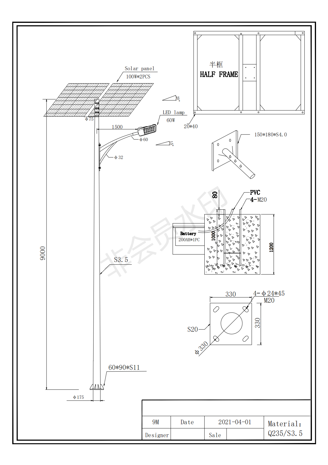
60 watt solar street lamp with controller
2 x 100w Solar panels
9 meter pole
| Components | Reference Photo | Specification | Q’ty in unit |
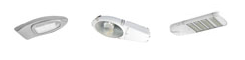
| Led Lamp | Model:ECO-60W 60W,imported USA Bridgelux LED chip, efficiency >170lm/w,life-span 100,000 hours, anodized aluminum,IP66 |
1 pc | |
| Poly Solar panel | Model:100P 100W Poly solar panel,A grade solar cell,high conversion efficiency,25 years at 85% of minimal rated output power. |
2 pcs | |
| Gel Battery | Model:GB200Ah 200Ah/12V,Gel type,free maintenance,deep cycle Life-span: >6 years |
1 pc | |
| Solar Controller | Model:PWM 10A 10A,12V/24V auto-sensing,light on+time intelligent control,high efficient and accurate charging control,IP68,various protections,with LED driver integrated |
1 pc | |
| Battery box | Model:BAB200Ah 200Ah/12V,Gel type,free maintenance,deep cycle Life-span: >6 years |
1 pc | |
| Pole (Whole set) |
9m height,75mm dia,Q235 steel,high wind resistance,anti-rust, hot-dip galvanized and Industrial marine painted, with fixing bracket and lamp arm,life-span>20years |
1 set | |
| Cable | Model:CB International standard cable,used for solar powered lighting connection,complete set |
1 set |